
Information
- Australian Adjuster
-
Over the years company have made a lot of stuff for the top guys to personalize their bikes. Chad Reed is one of the guys that knows what works for him and has his bikes setup that way. One of his requirements is having a reverse rotating cable adjuster when running a cable clutch. He has ridden for blue, red, yellow and green teams over his career and company have been there making the “left hand adjuster” parts for him. As a side note, it looks like he could have benefited from one of new transponder mounts.

Here is an off the rack RC-8 perch. The perch assembly is the platform to make a heap of rider preference refinements. Company can make special shaped levers with any pivot location. There are different materials available to produce the special shapes from. The refinement offered here is an adjuster that rotates in the opposite direction from standard.

This view makes it easier to get what the “standard rotation” is. Since the beginning of higher spec levers, (Magura late 60’s?), the adjusters have been right hand thread as shown by the green arrows. This rotation matches common machine tools used in producing the parts. A left hand thread, reverse rotation, requires special taps and short production runs of mating parts which adds to cost.

What is a left hand thread? Shown here is the angle of the thread comparing a left and right hand thread. They are dimensionally identical while having opposite rotations to tighten/loosen.

Since the parts are identical in size and color we emboss the “L & H” right on the parts so there is no confusion.

To the untrained eye this looks like the standard adjuster. It installs in about two minutes and may refine your bike to suit you better.

- Hose Bolt Gaurd
-
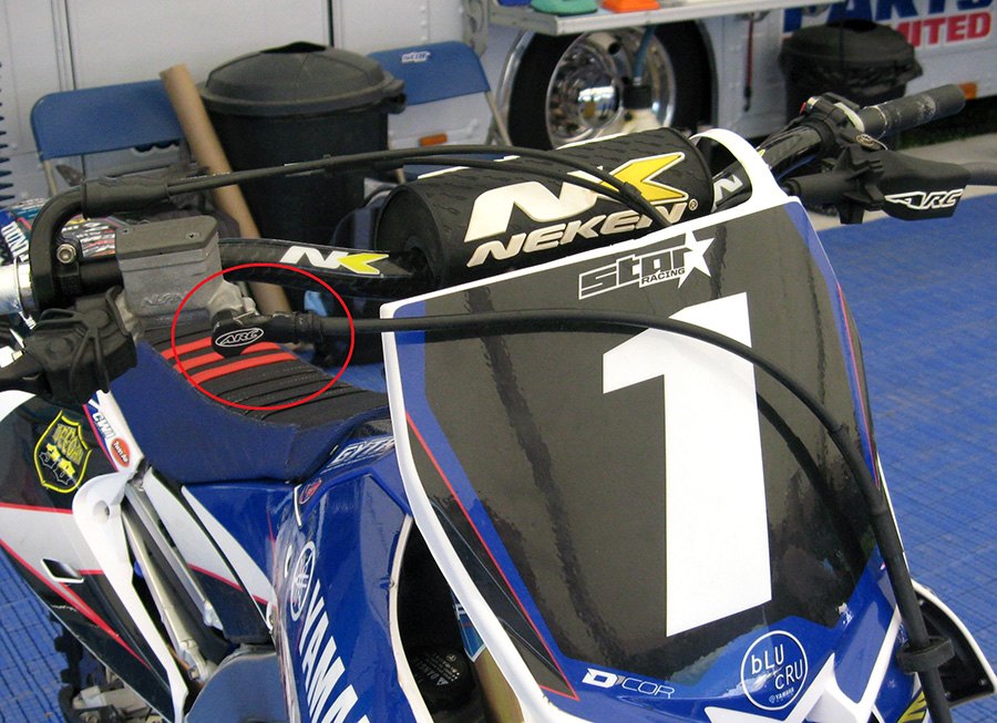
The red circle is highlighting the brake hose bolt guard. Company are developing a brake master cylinder with many adjustable features. One of the issues that will be solved on the new assembly is better protection for the pressure tube and hose bolt. Shown in this image is a test part to see how much abuse is thrown at the master cylinder. Company ty-rapped it on Jeremy Martins’ bike at Millville in ’15 and were surprised to see how badly it got roosted in just two motos. After seeing the abuse, company decided to make it into a production part called the “bolt guard”. If a rock impacts the bolt, the sealing washers can lose their seal and you have no front brake. The same issue happens when the bolt gets bent except then you will need a new master cylinder too since the threads may get trashed as well.

After two motos the guard had many small pits and scratches from sand and rocks in addition to being bent upwards. It looks like the part was tested at the right time since he won on the day and by the looks of this guard, it may have gone the other way without it! This product won’t win a race for you, it may keep you from losing.

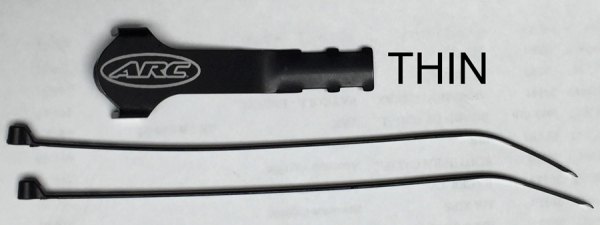
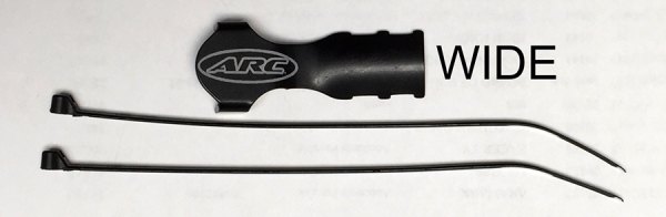
There are two types of hoses most commonly found on master cylinders that have the hose on the front. The left image is the THIN style and is seen on current Yamahas. It has just the hose end with no protecting rubber insulator. The image on the right shows the WIDE style that is used on current Suzuki’s and Kawasaki’s. The large rubber insulator is how to tell them apart. Regardless of manufacturer, year or brand, just pick the THIN or WIDE guard that matches your brake hose.


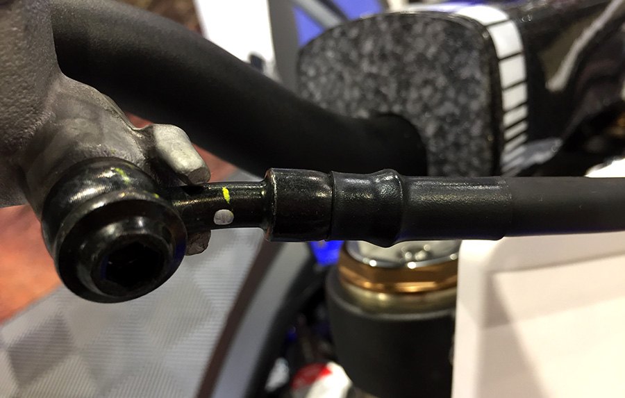
Here is the THIN guard installed. A small gap between the guard and bolt seems to work better than being flush against the bolt. The guard is soft to absorb damage so it is easy to bend by hand to get the fit shown above.


The same applies for the WIDE guard. Make sure you use the supplied ty-raps since they are nylon and much tougher than the hardware store variety.
- Insert Levers
-

The silver “knee” highlighted here is one of the first insert levers ever tested. When you live on a motorcycle as much as the top pro’s do, the smallest aggravation is huge. The front brake must be a sensitive area due to all the special parts we have made to accommodate. The insert lever refines the feel of the brake or clutch without needing a full machine shop to make a change.
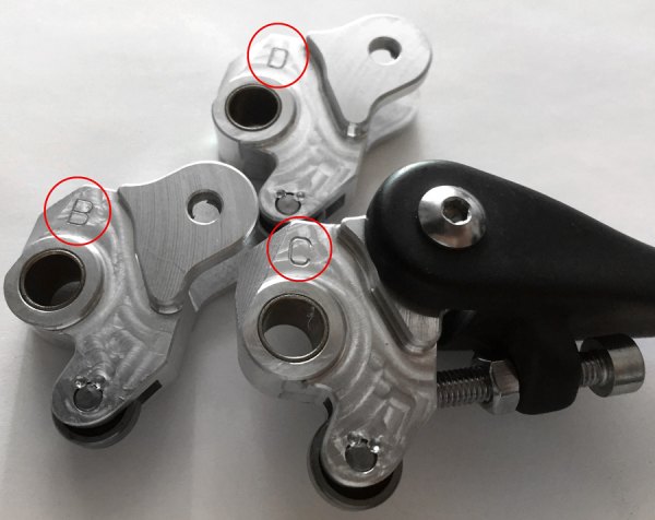
The distance from the lever pivot center to point of contact with the master cylinder piston is the ratio. Most stock brake levers have a ratio around 15mm’s. The ratio drastically effects how the brake feels and functions. Above left is the early method of changing the ratio with a ball bearing at the point of contact. This style vastly improved feel by just adding the bearing. Instead of metal to metal skidding, this lever rolled across the face of the piston. Different ratios are achieved by adding a .5mm different location of the bearing. The right image shows some pushrod style brake levers with the dimple machined in different locations. Shown are 13.5mm, 15mm and 16mm ratios for a CR master cylinder.
On the left is a tray of blank Magura hydraulic clutch knees. On the right is the shelf with all of the blank knees waiting a special ratio. You can see we have quite the collection just waiting for the phone to ring. It was very frustrating!!! We would get a call from a riders mechanic requesting a different ratio than the rider was using that day. I would go in the shop and tear down a setup to make a handful of different ratio knees. They would be sent red label to get there the next day. By the time they got the lever on the bike a day or three later, the conditions were not the same. The ratio lever allows ratio changes on the spot in a couple of minutes.

This is the solution to making ratio changes on the quick. Company added a box to house the replaceable inserts. Each insert has a different ratio and by rotating 180 degrees you have another ratio.
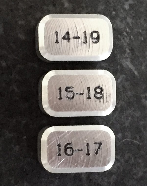
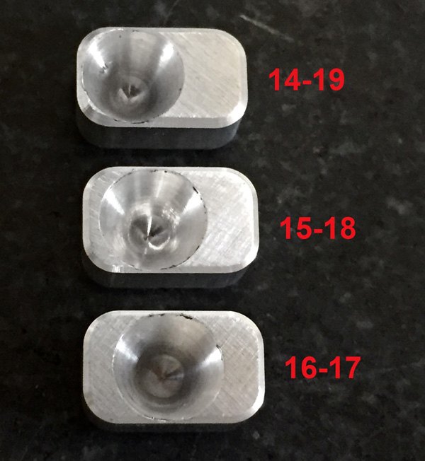
The inserts are marked with the corresponding ratio. On the backside you can see the different location of the dimples that create the ratio.
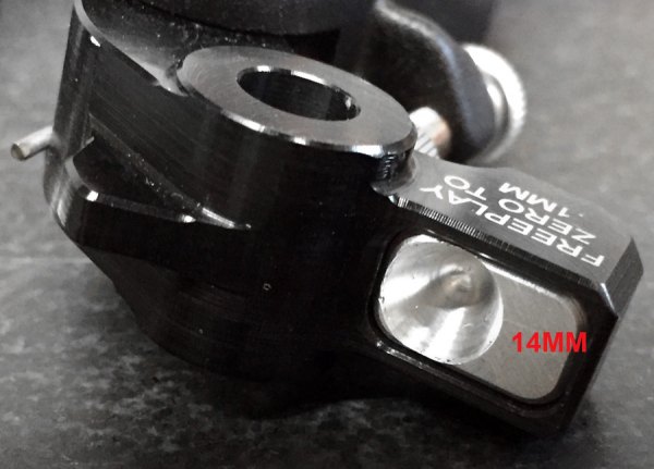
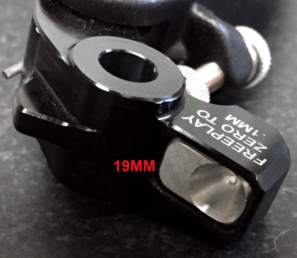
Shown is a 14-19 insert in two orientations. The engraved number closer to the lever pivot is the functioning ratio. This adds another element of setup to the bike. If the conditions are dry and slick you can back off the brake ratio to prevent locking the wheel. If the dirt is like chocolate cake then increase the ratio so you can take advantage of the extra power.
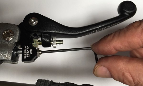
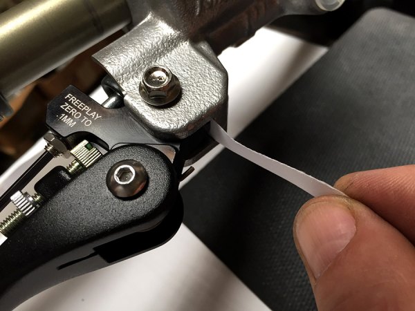
Each time an insert is changed the freeplay must be adjusted. As the angle of the pushrod is altered with a ratio change, the distance also changes and needs to be adjusted. Depending on whether a “harder” or “softer” ratio is selected you may have too much play or too much pre-load. It is very simple and takes less than 30 seconds. Back off the locknut of the adjuster screw. Loosen the set screw until some freeplay is felt. Place a piece of paper at the stop contact point. Turn the adjuster in until drag is felt on the paper and tighten the locknut. Be careful the first few times you activate the brake because it will function differently than the previous setup.

The insert levers refine control function. For over 15 years company have been making special ratios for the top riders and now you can have the same adjustment options as the factory guys. The brake levers can go from feeling like there is air in the system with a 14mm insert to “something is wrong, the lever is hardly moving” with a 19mm insert. The clutch levers compensate for Rekluse style clutches. The slipping type clutches seem to need a pinch more “pull” at the lever to get full disengagement. Hydraulic clutches benefit greatly from the ability to overdrive the master cylinder and get that “pinch” more pull needed.