Overview of Ignition Technology
- The Stages of a Spark Discharge
-
The ignition process is key to the operation of internal combustion engines. Four-cycle engines require external combustion, and this is accomplished by discharging electrical energy through a spark gap. Heat transfer and gas ionization (splitting apart of gas molecules) caused by the spark discharge initiate a flame kernel. The flame kernel then grows into a flame front that spreads through the combustion chamber. The stages of a spark discharge include breakdown, arc, and glow discharges.
Break Down
Most engines require nearly 12,000 volts to fire the spark gap. When this voltage level is reached, a very high current flows for several hundred nanoseconds, an almost inconceivably short period of time, as energy stored in the capacitance of the coil, secondary wiring, and spark plug is rapidly discharged. Because the break down phase is so short, it accounts for only a small percentage of the total ignition energy. To better put this into perspective, at 6,000 RPM the crankshaft rotates less than 1/100 of a degree in 200 nanoseconds!
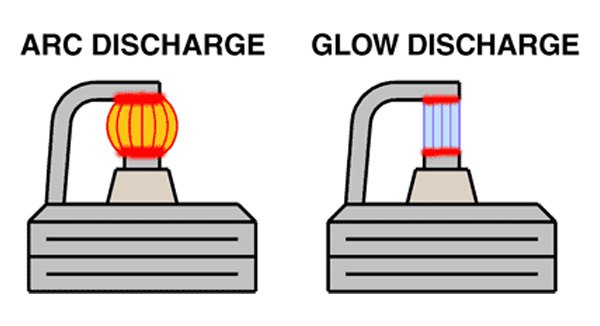
Arc Discharge
The break down phase is followed by an arc discharge. An arc discharge requires a considerable current flowing in the gap, usually on the order of several hundred milliamps. During the arc phase, the voltage across the gap drops to about one hundred volts. An arc discharge is very visible and high levels of energy are transferred to the flame kernel near the center of the spark gap. The duration of the arc discharge for a conventional ignition is usually no more than a few microseconds. Again, to put this into perspective, at 6,000 RPM the crankshaft rotates through less than 1/10 of a degree in 2 microseconds!
Glow Discharge
A glow discharge is less intense and the sustaining voltage across the gap is higher. A neon light is a good example of a glow discharge. It looks nice, but it doesn't generate a lot of heat. Much of the energy in the glow discharge is lost heating the electrodes or ionized gas near the electrodes. Conventional ignition systems have a short arc phase (some microseconds) after the initial breakdown followed by a glow discharge that lasts 1-2 milliseconds. At 6000 RPM, the crankshaft rotates through 36 degrees in one millisecond.
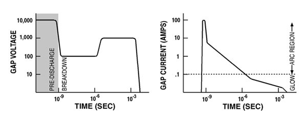
The two graphs below show the behavior of the spark gap voltage and current as a function of time for a typical ignition system. Note that the graphs are logarithmic (axes stretch out towards zero). On the time axis, 10-9 represents nanoseconds, 10-6 represents microseconds, and 10-3 represents miiliseconds in scientific notation.
- Terms Used to Rate Ignition System Performance
-
Peak gap current - the maximum current flowing during the arc or glow discharge. Peak gap current is a critical determinant of ignition system performance. One can easily measure the peak gap current for arc and glow discharges, but accurate measurement of gap current during the breakdown phase is very difficult.
Spark duration - the elapsed time from beginning of the breakdown phase to the end of the glow phase. Spark duration is usually measured in microseconds or milliseconds. However it is also useful to think of spark duration in terms of degrees of crankshaft rotation at a particular RPM.
Available voltage - also known as the open gap voltage. This is the maximum voltage that the ignition system can generate. It is measured by opening the spark gap until no spark occurs. There is no relationship between the available voltage and the actual voltage across the spark gap once the spark fires. Many myths and misconceptions exist about coil "voltage." Coil vendors often claim ridiculous figures such as 50,000 volts. This is the maximum voltage the coil generated in a lab and has little bearing on anything in the real world.
Firing voltage - this is the voltage required to fire the spark gap. The worst case requirement usually occurs starting a cold engine and may reach 20,000-25,000 volts. A larger spark gap and/or higher cylinder pressure will increase the required firing voltage. Most engines with correctly gapped spark plugs have a required firing voltage in the range of 8,000-12,000 volts. Once the spark is fired, the sustaining voltage drops to a low value, usually no more than a thousand volts.
Ignition energy - the most common unit of measurement is the millijoule. Energy is the product of voltage x current x time. One millijoule corresponds to a current of one milliamp flowing through a voltage drop of 1000 volts for an elapsed time of one millisecond. One has to be very careful when comparing ignition energy measurements. Some vendors report "primary" energy. This is the energy stored in the ignition system and has no direct relationship to the energy dissipated in the spark gap.
Cyclical variation - this is a technical term for the misfiring. All engines exhibit some variation in power output for successive cylinder firings. This variation results from slight differences in the rate of pressure rise during combustion. Cyclical variation cannot be directly observed or measured on a dyno; accurate determination involves the use of in-cylinder pressure sensing. A unstable flame front can increase cyclical variation. High energy ignition systems can reduce cyclical variation by promoting rapid growth of the flame kernel into a stable flame front.
- Types of Ignition Systems
-
Single Fire and Dual Fire
Single fire and dual fire refers to the number of times the spark plug fires during each four stroke cycle. The terminology is somewhat unique to Harley-Davidson® engines and is by no means consistently applied. For example, Custom Chrome Industries, one of the largest distributors of Harley-Davidson® aftermarket parts, uses the opposite terminology. Their single fire systems correspond to what most other companies refer to as dual fire.
With the exception of the new Twin-Cam 88 and late model Sportster 1200 engines, all carbureted Harley-Davidson® engines have been dual fire. A single coil winding with two high voltage output terminals fires the spark plugs on both cylinders simultaneously. Each plug is fired twice during each four stroke cycle. This approach was used to cut costs as it eliminates the need for a distributor or a second coil and additional electronics. Dual fire results in a number of potential problems.
Most late model automotive engines are distributorless. Many of these engines use coil packs where a single coil winding fires two spark plugs. When one spark plug fires on the compression stroke the other spark plug is firing on the exhaust stroke. This approach is termed "wasted spark" and is widely used. The wasted spark always occurs on the exhaust stroke because the engines have even firing intervals (i.e. 90° for a V8) and cylinders are always paired so that the pistons are 360° out of phase (i.e. one on the compression stroke when the other is on the exhaust stroke). The wasted spark causes little energy loss and no harmful effect on the exhaust stroke.
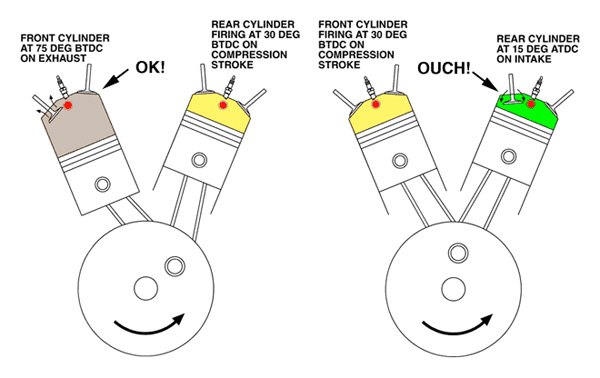
The situation is quite different with a dual fire ignition on a Harley-Davidson® V-twin engine with 315° and 405° firing intervals. The graphic below shows what occurs. When the rear cylinder is fired on the compression stroke, the front cylinder is on the exhaust stroke - which is OK. But when the front cylinder is fired on the compression stroke, the rear cylinder is already on the intake stroke! Under some conditions, a combustible mixture may exist in the rear cylinder at this point and the wasted spark causes a backfire through the carburetor. Long duration camshafts and improper carburetor jetting can contribute to the problem. Additional information on this subject may be found on the Mikuni web site.
A single fire ignition eliminates the backfire problem and enhances idle quality. The single fire ignition uses separate coil windings and electronics to fire each spark plug independently. Spark firing occurs only on the compression stroke. Conversion of older carbureted Harley-Davidson® engines to single fire is highly recommended. There is no downside to single fire, other than the cost of the conversion.
Inductive Discharge
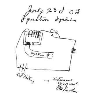
All Harley-Davidson® original equipment and all the popular aftermarket ignition systems, including Twin Tec, are of the inductive discharge type. Charles Kettering first described the principle in 1908. His original notebook drawing is shown below, courtesy of General Motors.
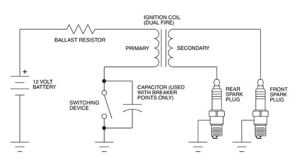
Inductive discharge ignition systems operate on the principal of energy storage in the magnetic field of the coil primary windings. A switching device, such as mechanical breaker points on early models or a transistor on modern electronic systems, applies battery voltage to the coil primary. The applied voltage causes current flow to build up and store energy, in the form of a magnetic field, in the primary windings. Stored energy is proportional to the coil inductance times the square of the current. The diagram below shows a typical Harley-Davidson® dual fire system. Dual fire means that both spark plugs are fired simultaneously. A separate ballast resistor is shown for clarity. Ballast resistance limits
the coil current. In actual systems, the resistance of the coil primary winding serves as the ballast resistor.By the laws of physics, an inductor tries to maintain a constant current flow. When the switching device turns off, the primary current flow is disrupted. Current flow is transferred to the secondary - firing the spark gap. Current continues to flow until all the stored energy has been used up. It is important to understand that only a fraction of the available stored energy is actually dissipated in the spark gap. Much of the energy is lost as heat generated in the coil windings, spark plug wire, and even the resistance element within the spark plug.
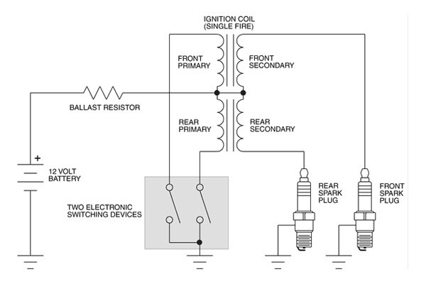
Inductive discharge systems require a finite period of time to recharge the coil in between firing events. In automotive applications with distributor ignition, this is a significant disadvantage. A V8 engine with distributor ignition requires the coil to fire a spark every 90 degrees of crankshaft rotation. The ignition energy rapidly drops off above 5,000 RPM because insufficient time exists to recharge the coil. This is not the case with a V twin engine. Even a basic dual fire system with one coil servicing both cylinders has firing intervals of 315 and 405 degrees. With single fire, independent coil sections (often combined in one housing - but independent nonetheless) each fire every 720 degrees. That leaves a lot of time to recharge the coil. A typical Harley-Davidson® single fire system is shown below. The shaded block (two independent electronic switching devices) represents the ignition module. For Evolution® and Shovelhead® applications, ballast resistance is used to limit coil current. In these systems, the resistance of the coil primary windings serves as the ballast resistor. Primary resistance is typically 3 ohms. Newer Twin Cam 88® applications use a coil with very low (about .5 ohm) primary resistance. Coil current is limited electronically within the module by restricting the charging time.
Capacitive Discharge
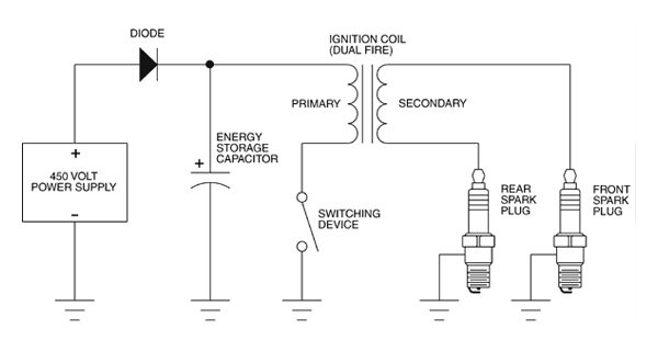
Capacitive discharge (CD) ignition systems are widely used in automotive racing applications with high RPM requirements. The diagram below shows a simplified CD system. A special high voltage power supply charges a capacitor to 450 volts or more. Energy is stored in the electrostatic field within the capacitor and is proportional to capacitance times the square of the applied voltage. An electronic switch discharges this stored energy into the coil primary. A high voltage pulse then appears across the secondary windings and fires the spark gap. CD ignition systems are more complex, more expensive, and take up more space than an inductive system due to the requirement for the special high voltage power supply.
Several vendors including Crane, Jacobs, and MSD have attempted to introduce CD ignitions for Harley-Davidson® applications. None of these were accepted by the market, outside some limited racing applications for the MSD unit. The systems were too big and too expensive and provided no measurable benefit for the vast majority of potential users.
- Ignition Coils
-
For Harley-Davidson® applications, the ignition coil plays a very limited role as far as engine performance and aftermarket coils provide no measurable benefit. There are only two exceptions:
· Conversion of older Evolution® and Shovelhead® engines to single fire operation which requires replacement of the original equipment coil. Daytona Twin Tec recommend high output single fire coil part number 2005.
· Dual plug heads. Older Evolution® and Shovelhead® engines have inefficient combustion chambers designs with relatively slow flame front propagation. Conversion to dual plug (two plugs per cylinder) generally results in a modest performance improvement. One approach is to use two dual fire coils, but this requires mounting a second coil. An alternate
approach is to use a four tower coil, such as the Dyna DC6-4.Two coil constructions are used for Harley-Davidson® applications: one piece cast epoxy and molded plastic. The older cast epoxy coils are prone to developing cracks that allow moisture infiltration resulting in premature failure from arcing between layers of the coil windings. Newer coils use a molded plastic shell with the core and windings impregnated with epoxy or urethane material. This is a far superior construction that offers better long term reliability.
Regardless of claims made by some vendors, there is very little difference between the original equipment and aftermarket coils. All coils for Evolution® and Shovelhead® electronic ignition applications require about 3 ohms primary resistance to limit coil current. Present aftermarket coils for the new Twin Cam 88 engine use low primary resistance (about .5 ohms) and are manufactured by the same company (Marshall). The internal winding and core details are very similar to the original equipment coil. The only difference is in the styling of the plastic housing. These coils should be considered cosmetic appearance items, not performance parts.
- Spark Plug Wires
-
Three types of spark plug wires are commonly available: original equipment style carbon core suppression, low resistance spiral core, and solid core. Carbon core suppression wires cause some energy loss due to their high resistance (about 5,000 ohms/foot). Replacing carbon core suppression wires with low resistance spiral core wires only increases spark energy by about 10%. Contrary to any claims, you will not see a performance improvement by changing spark plug wires. On the other hand, carbon core wires can deteriorate over time and any wires more than a few years old are candidates for replacement. If you are going to install new spark plug wires, buy a set of low resistance spiral core wires. Most are less than 500 ohms/foot. At that point, almost no energy is lost in the wire. There are some new versions with very low resistance (50 ohms/foot), but the advantage is insignificant for the short lengths encountered in motorcycle applications.
Do not use solid core spark plug wires. These radiate excessive electromagnetic noise that will cause radio interference and may even cause the processor in the ignition module to glitch. Daytona Twin Tec do not recommend Nology® spark plug wires. These have a partially shielded jacket that forms a energy storage capacitor. When the spark plug fires, energy stored in this capacitor is rapidly discharged causing a short but intense arc discharge. There may be some advantage if the spark plugs are fouled, but the Nology® wires tend to radiate more electromagnetic noise.
- Ignition Requirements for Harley-Davidson® Engines
-
Harley-Davidson® engines are not very sensitive as far as ignition energy when operating at wide open throttle. This statement is based on years of experience and many dyno tests. In no case, did Daytona Twin Tec ever observe any change in power output related to ignition energy.
The original equipment (OE) electronic ignitions on the older Shovelhead® and Evolution® engines are perfectly adequate as far as ignition energy. These OE systems are dual fire. Changing a Shovelhead® or Evolution® engine to an aftermarket single fire system brings improvements in starting and reduces the occurrence of backfiring through the carburetor. All the new Twin Cam 88 engines already come with an OE single fire ignition.
Performance improvements with aftermarket ignitions systems come from optimizing the ignition timing and raising the RPM limit (with appropriate valvetrain modifications). All Harley-Davidson® engines are fairly sensitive to ignition timing. Due to the great number of possible variations in carburation, compression ratio, exhaust tuning, head design, and camshafts, it is impossible to make a unit with a single optimum advance curve. Twin Tec units are designed to allow a wide range of adjustment to cope with these variations. All Daytona Twin Tec units also allow the user to program a custom advance curve. An experienced engine builder or dyno tuner can use this capability to unlock a few more horsepower. The
table below summarizes the effect of various engine parameters on the ignition advance requirement.Engine Parameter Volumetric Efficiency Flame Front Velocity Combustion Time Ignition Advance Requirement Engine RPM VE peaks near torque peak Increased at VE peak Reduced at VE peak Less relative advance at VE peak. However, predominant effect is that more advance is required as RPM increases due to less time for crank to sweep through a given angle - thus requiring spark initiation at a greater angle BTDC Increased compression ratio Minimal effect Increased Reduced Less advance More radical camshaft (increased duration and overlap) Less at low RPM; greater at high RPM Less at low RPM; greater at high RPM Less at low RPM; greater at high RPM More advance at low RPM; less advance at high RPM Improved exhaust scavenging or less back pressure Varies throughout RPM range Lower levels of exhaust gas residuals in cylinder increases velocity Reduced Less advance within the RPM range where exhaust is most efficient Improved intake system efficiency (bigger throttle body or low restriction air cleaner) Generally greater at high RPM for H-D® engines Increased Reduced Less advance Increased fuel octane No direct effect Reduced; less likely to reach knock limit Reduced More advance; increased knock limit Air/fuel ratio No direct effect Optimum near stochiometric 14.7 A/F ratio Optimum near stochiometric 14.7 A/F ratio More advance required for rich mixtures Improved fuel atomization Minimal effect Small fuel droplets burn faster Reduced Less advance Increased intake air temperature Lower Increased; may reach knock limit where end gases ignite Reduced Less advance; lower knock limit as temperature increases Increased humidity \Slight reduction as water displaces air Reduced Increased More advance. Extreme example is water injection used to increase knock limit Increased cylinder head temperature Minimal effect Increased; may reach knock limit where end gases ignite Reduced Less advance; lower knock limit as temperature increases Spark plug position in head; number of spark plugs No direct effect Minimal effect Affected by distance from plug to farthest cylinder wall. Ideal location for single plug is center of squish area Less advance for centered spark plug or dual spark plug designs Greater bore/stroke ratio \Minimal effect unless valve shrouding occurs in large bore designs Short stroke increases rate of compression and results in higher velocity Large bore requires more time to burn from spark plug to cylinder walls Very long stroke or large bore (oversquare) engines may require up to 10° more advance than an equivalent CID engine with optimum bore/stroke ratio Combustion chamber design with high squish and swirl Minimal effect High swirl increases velocity High squish designs take less time to burn to farthest reaches Less advance for efficient combustion chamber designs - Leading Edge Technology
-
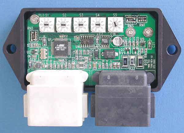
The picture above shows Daytona Twin Tec TC88 ignition before encapsulation. All Daytona Twin Tec products use surface mount technology (SMT). SMT is based on miniature, low profile parts that are directly soldered to the surface of the printed circuit board. SMT is the enabling technology behind camcorders, cell phones, and laptop computers. SMT reduces size, weight and cost. Reliability is greatly increased because the low profile surface mount parts are rigidly attached without leads that can break from shock and vibration. The majority of components in Daytona Twin Tec designs are "0603" size (.06 x .03 inch), not much larger than a grain of sand. The large black chip near the left side of the board is an Atmel ATMEGA processor. The ATMEGA chip includes a math accelerator and allows self-reprogramming of FLASH memory.