
Frequently Asked Questions
- Brake Kits
- Rotors
- Brake Pads
- Calipers
- Pedals
- Master Cylinder
- Brake Fluid
- General Information
- How do I measure my axle off set?
-
Measure the distance from the face of your axle-housing flange (where the drum brake backing plate is attached) to the outer face of the axle flange where the wheel studs come through.
- How do I measure & determine my axle flange?
-
There are 4 bolts that hold the drum brake backing plate to the axle housing flange. Measure the distance between the bolts, horizontally and vertically, center to center. Compare these measurements with the following dimensions: (A) Overall width; (B) Overall height; (C) Top bolt spacing; (D) Lower bolt spacing; (E) Front bolt spacing; (F) Rear bolt spacing and (G) the diameter of the bearing or tube. Using those measurements you can compare it with the axle housing flange chart in the website.
- What is the basic difference between a drag kit and a pro street kit?
-
Drag kits use solid steel rotors (or optional drilled rotors) and yield high brake torque, yet are very lightweight. They are engineered to the absolute minimum in rotating and un-sprung weight, where all that is required is a single stop at the end of a drag run. The lightweight steel rotor is not designed to absorb and release the heat generated when driving in normal traffic and will warp quickly when used on the street. Pro street kits use cast iron rotors that are .810” thick, weighing 7.9lbs. Their vented design and cast iron material allows them to absorb and release the heat generated when driving in normal traffic. These kits offer a substantial weight savings over factory disc brakes due to the use of aluminum hubs, rotor adapters, calipers and brackets, while the vented cast iron rotors offer long term durability for street use.
- Do bolt-on brake kits require any alteration to the spindles or rear axles?
-
Front brake kits occasionally require minor modifications to the spindle such as drilling and tapping a bolt hole to a larger size. Rear axle kits require no modifications provided that you purchase the correct kit for your housing flange and offset.
- Do installation instructions come with Wilwood brake kits?
-
Yes. With the exception of certain custom applications, all Wilwood kits include step-by-step installation instructions. Please note that brake kits and components should only be installed by experienced mechanics with a good understanding of brake systems.
- What bolt patterns and stud sizes are available in Wilwood bolt-on brake kits?
-
Front kits, which include Wilwood aluminum hubs, have ½" studs. With a few exceptions, hubs are manufactured to accept both 5x4.50" and 5x4.75" bolt patterns. Hats used in front kits are generally drilled to fit over the original OEM studs.
- How much better is braking going to be if I use your product over stock?
-
Most modern stock brake systems work well for average daily street driving and an occasional 60-0 or 80-0 stopping. Typically performance enthusiasts who occasionally compete in racing events, push the stock brake system beyond its capabilities. Driving style, and other performance modifications such as increased horsepower, tire and suspension upgrades, etc., can quickly overwhelm stock brakes. A big brake kit will provide increased heat capacity, which means substantially more resistance to brake fade and caliper distortion with multiple stops from high speed. A firmer pedal due to stronger and stiffer components, as well as better modulation characteristics are also benefits of a properly balanced brake upgrade.
- Will your bolt on brake kits work with the factory power booster and master cylinder?
-
Yes, Wilwoods kits are designed to work optimally with your factory setup.
- What's the difference between slotted and drilled/slotted rotors? Which rotor will be best for my application?
-
PSlots or grooves in rotor faces are partly a carryover from the days of asbestos pads. Asbestos and other organic pads were prone to “glazing” and the slots tended to help “scrape or de-glaze” them. Also, cross-drilling and/or slotting the rotor for racing purposes was beneficial by providing a way to expel the gasses created when the bonding agents employed to manufacture the pads began to break down at extreme temperatures. This condition is often referred to as “outgassing.” When it does occur, the driver still has a good firm brake pedal, but a significant reduction in friction. Normally this only happens at temperatures witnessed in racing. However, with today’s race pad technology, “outgassing” is no longer a concern with pads designed for racing. So in the final analysis, drilling and slotting rotors has become popular in street applications for their pure aesthetic value. Wilwood provides rotors slotted, drilled or plain. For most performance applications, slotted is the preferred choice. With certain pad material, slotting can help wipe away debris from between the pad and rotor as well as increasing the coefficient of friction between the rotor and the pad. A drilled rotor provides the same type of benefit, but is more susceptible to cracking under severe usage; however, for street and occasional light duty track use, they will work fine. For more severe applications, we recommend slotted rotors.
- Does my pad bedding process change at all if I have e-coated rotors?
-
No, the bedding process is the same. Remember, proper break-in of pads and rotors is extremely important. Not doing so, can cause permanent damage to rotors and adversely affect overall brake performance. Pads and rotors interact with each other to provide efficient brake performance. The break-in or bed-in procedure is done to condition the pad/rotor interface. Depending on the pad used, more or less pad material is uniformly transferred onto the disc as a thin film. The resins and bonding agents in some pads need to be heat cycled to work properly as well. By not properly bedding-in pads, uneven pad material deposits can occur that may cause a vibration. Improper wear characteristics may also show up on either the pads, or rotors, or both.
- What do the black rotors look like once they are bedded-in?
-
The annulus (where the pad comes in contact with the rotor) is quickly stripped of the e-coating and appears the same as any iron rotor. The e-coating remains in the radius around the drilled holes, and in the slots providing a nice contrast and high visibility of the drilled and slotting pattern of the rotor, as well as protecting those areas from rust.
- Why are my rotors black, I wanted zinc?
-
Wilwood uses a process called “E-Coating” to protect our rotors from corrosion. E- coating is another name for electrocoating, electropainting, or electrophoretic lacquering. It is used to deposit a protective coating as opposed to a metal such as is deposited by electroplating. Parts are dipped into a vat of the e-coat material and are electrified in order to promote a reaction at the surface, which deposits the protective agent. Through this process, we ensure that all exposed surfaces are protected from corrosion, providing the very best in protection. You can still order Zinc plated rotors as an option, but keep in mind that the zinc coating is more expensive and offers less rust protection than e-coat.
- What kind of brake pads should I use?
-
The best type of brake pad for any car will depend on both how the vehicle is operated and the vehicle type. For example, factors like vehicle weight, brake temperature, and how the vehicle will be used should be considered when choosing the proper brake pad. Wilwood stocks multiple brake pad compounds for most popular cars and trucks, and has the right brake pad for your street performance application.
- Do you make a pad that will work equally well for both street and track use?
-
The short answer is no pad will work "best" in both environments; there will always be a compromise in one area of operation. Pads are asked to do a number of different tasks in different situations. The following are things you should consider to help you pick the best pad.
- Stopping performance when cold. How well does the pad grip on the first stop when the system is at ambient temperature?
- Stopping performance when hot. How the pad reacts in higher temperature such as on the track?
- Pad Life. How long will the pads last in a given driving environment?
- Rotor Life. How aggressive is the pad on the rotor?
- Noise. Does the pad squeal?
- Dust. How much dust does the pad generate, how easy is it to clean?
If you run one pad on both the street and the track, you will have to compromise performance in one way or another on all the above. We suggest changing to a track worthy pad for track events, with a proper bed-in before the event. The system will need to be bedded-in again when the street pads are re-installed for the street.
- Will larger brake pads improve my stopping distances?
-
Not necessarily. A larger pad of the same compound in the same location as a smaller pad will not yield shorter stopping distances. The amount of pressure applied, the pad friction coefficient, and the diameter of the rotor at which that pressure is applied, determine the torque reaction, or stopping force. A larger pad does not apply more pressure, only the same pressure over a bigger area. The size of the pad does matter in terms of heat capacity and wear rate. A larger pad will absorb more initial heat, hence less thermal shock, and have better wear characteristics resulting in longer pad life.
- How do I retract the caliper pistons to change pads?
-
Before new pads can be installed, the pistons need to be pushed back into the caliper body. There are several ways you can accomplish that without requiring special tools. However, be very careful during retraction because you don’t want to damage the face of the piston where it contacts the backing plate of the pad. (Normally the rotor will be loose on the hub with the wheel removed.) By working the rotor back and forth, you will be able to push the pistons back enough to remove the used pads without risking damage to the piston(s). This is particularly important in the case of significant rotor wear, in which case there is a raised ridge on the outer edge of the rotor face that makes sliding the pad out of the caliper difficult. The used pads being removed from the caliper can be used as a tool to “lever” the pistons back into their bores. Remove one pad from the caliper while leaving the other used pad in place. Rotate the removed pad 90 degrees and re-insert it halfway into the caliper perpendicular to its normal axis. The center of the pad will rest on the outer edge of the rotor, creating a fulcrum on which the pad can rotate. Keep the pad face toward the rotor and using the pad as a lever, press both pistons in at the same time. It is important to retract both pistons at the same time so they are compressed evenly. If you have trouble retracting the pistons, you can open the associated bleed screw with a hose leading to a tray or bottle of fluid, and it will ease the resistance. Remember, you will need to bleed the system if you open the bleed screw. Push the pads in as far as possible, close the bleed screw, remove the used pad and install the new pad. Repeat the process on the other side of the caliper. You can also use other tools to push in the pistons, including special tools designed specifically for that purpose; however, unless you replace pads on a regular basis, it is not worth the cost to purchase them. One final caveat; keep an eye on the brake fluid level in the master cylinder reservoir. If the system was bled and topped off when the pads were worn, you might push enough fluid back through the system to overflow the master cylinder.
- What is the proper pad bedding procedure?
-
Once the brake system has been tested and determined safe to operate the vehicle, follow these steps for the bedding of all new pad materials . These procedures should only be performed on a race track, or other safe location where you can safely and legally obtains speeds up to 65 MPH, while also being able to rapidly decelerate. Begin with a series of light decelerations to gradually build some heat in the brakes. Use an on-and-off the pedal technique by applying the brakes for 3-5 seconds, and then allow them to fully release for a period roughly twice as long as the deceleration cycle. If you use a 5 count during the deceleration interval, use a 10 count during the release to allow the heat to sink into the pads & rotors. After several cycles of light stops to begin warming the brakes, proceed with a series of medium to firm deceleration stops to continue raising the temperature level in the brakes. Finish the bedding cycle with a series of 8-10 hard decelerations from 55-65 MPH down to 25 MPH while allowing a proportionate release and heat-sinking interval between each stop. The pads should now be providing positive and consistent response. If any amount of brake fade is observed during the bed-in cycle, immediately begin the cool down cycle. Drive at a moderate cruising speed, with the least amount of brake contact possible, until most of the heat has dissipated from the brakes. Avoid sitting stopped with the brake pedal depressed to hold the car in place during this time. Park the vehicle and allow the brakes to cool to ambient air temperature.
- Does my brake pad bedding process change at all if I have e-coated rotors?
-
No, the bedding process is the same. Remember, the proper break-in of pads and rotors is extremely important. Not doing it properly, can cause permanent damage to rotors and adversely affect overall brake performance. Pads and rotors interact with each other to provide efficient brake performance. The break-in or bed-in procedure is done to condition the pad/rotor interface. Depending on the pad being used, more or less pad material is uniformly transferred onto the disc as a thin film. The resins and bonding agents in some pads need to be heat cycled to work properly as well. By not properly bedding in pads, uneven pad material deposits can occur that may cause a vibration. Improper wear characteristics may also show up on either the pads, or rotors, or both. For more information on bedding, please consult Wilwood's Tech Tip Guide.
- What is "uneven pad deposition," and how does it affect my brake performance?
-
Before new pads can be installed, the pistons need to be pushed back into the caliper body. The vast majority of modern brake pads are what is referred to as an adherent type of pad. The pad is designed to transfer a layer of pad material onto the rotor. When a sufficient and even layer of pad material is adhered to the rotor face, the pad material on the rotor, interacting with the similar material on the pad, creates the most efficient friction mechanism. The "like" materials, breaking against each other on a molecular level, provide the best braking performance. Problems occur when the pads are not properly bedded-in, i.e., an even layer of pad material is not deposited on the rotor and the brakes are used aggressively, or when the pads are overheated, e.g., using street pads on the track. The pad transfer occurs most efficiently at the pads optimal operating temperature. That means a higher temperature pad needs to be hotter to properly transfer material. If you have a high-performance pad and never run it hot enough to get a proper layer of material onto the rotor, it will never be properly bedded-in. Thus, even after several hundred miles of "normal" street driving, you can get uneven deposits on the rotor causing a vibration when you engage in some form of racing and heat the brakes. The other common scenario is over-heating the pads even if they are properly bedded-in. In this case, the pad material starts to break down and smear onto the rotor face, again causing un-even deposits. The other problem that occurs is when the system is really hot and you come to a complete stop and leave your foot on the brake pedal. In this instance, you get what is called "pad imprinting" where a small layer of material breaks off from the surface of the pad and literally can be seen as an imprint of the pad on the rotor face. This can occur in any state of the bed-in process. All of these scenarios leave very small, uneven layers of material on the rotor. All it takes is a few 10/1000's of an inch. It starts out almost imperceptibly, but as the pads start to skip over the high spots, more material is deposited on those areas, ever increasing the vibration until it becomes quite noticeable, even days after the event that started it occurred. The best way to avoid these problems is the proper bed-in of the system initially, and using the proper pads for your exact driving conditions.
- I have a shudder or vibration under braking. What should I look for and how can I fix it?
-
In order to better understand the likely cause of shudder and/or vibration, please see the above FAQ relating to un-even pad deposition. Obviously, turning the rotors will take care of it, but you will be shortening the life of the rotor and decreasing its ability to absorb and control heat, as there will be less mass in the rotor after turning. Wilwood has had very good success running an aggressive track pad at lower temperatures on the street in order to scrub-off the rotor surface. Wilwood has found the Polymatrix B race pad to be very effective. At lower temperatures it is very abrasive and does not become adherent until it reaches its optimal operating temperature. If it is used with a few firm stops at a time, not getting too hot so that you only remove material, not transfer more; it will often remove the source of vibration. WARNING: Do not leave an abrasive pad in the caliper longer than necessary to solve the problem. As soon as the problem goes away, change back to your street pad and re-bed them. Your rotors can be destroyed in under a week by leaving the abrasive track pads in on the street.
- Where can I get replacement brake pads for my Wilwood calipers?
-
Wilwood has a worldwide dealer network that stocks and sells replacement parts. A quick Google search can help you find a stocking dealer such as a local high-performance speed, hot rod or race shop, or you can buy them on-line through our website.
- Should rotors be turned before replacing brake pads or after a set amount of road service?
-
Not if they are still serviceable. In fact, the best way to bed your new pads is with a rotor that has already been bedded. The rotor is basically the radiator for your brake system. The larger the rotor for any given design, the better it cools. Each time you turn a rotor, you remove material; therefore, you remove some of its ability to cool. You should regularly inspect your rotors for conditions such as cracks or excessive wear and immediately replace them if they are defective or out of tolerance.
- Why do my brakes clunk or squeal when I apply them?
-
Some of the noises can be minimized; others are an unavoidable result of the incredible friction levels obtained in today's high-performance racing brake pads. Sounds that are mechanical such as clunks, bangs and rattles may be caused by missing or worn out "anti-rattle" devices that are designed to place a small amount of tension on the brake pad in the caliper, limiting its free play movement. The easiest way to silence these noises is to replace any missing or damaged anti-rattle clips. Squeal may emanate from a number of sources; however, it most commonly comes from a harmonic that develops between the caliper piston and the pad backing plate. Applying our noise absorption shims usually reduces the backing plate to piston squeal. Our noise absorption shims are an elastomeric dampening material over a steel shim, which installs between the pistons and backing plate. Noise absorption shims are available for both our Dynalite and Superlite brake pads. If further noise reduction is required, you may want to switch to our Polymatrix Q compound pads. Our Q compound pads were specifically designed for low noise and low dust. Accomplishing the goals of very low noise and dust requires that the pads have a lower coefficient of friction than our standard pads, and therefore you may notice a slight decrease in braking performance.
- What advantage is there in having a radial mount Caliper over a lug mount caliper?
-
Radial mount calipers and brackets offer a much more rigid mounting system than a lug mount design. The radial design also accommodates rotor diameter changes with a simple spacer rather than a whole new bracket. A customer with a 13” rotor kit that wants to upgrade to a 14” rotor would only require longer studs and spacers rather than a completely new taller bracket.
- Which is the more ridged Caliper, a two-piece or a monobloc?
-
Everything being equal, a properly designed two-piece caliper will flex less than a monobloc caliper. Stiffness is a function of the material’s modulus of elasticity. Steel bolts have an elastic modulus approximately three times that of aluminum bridges. There are some exotic aluminum alloys that were developed for F-1 racing that have almost the same elastic modulus as steel; however, they are expensive and not normally seen in after market brake kits. Steel has the added benefit of not losing its elastic modulus as things heat up. As a matter of fact, steel’s elastic modulus actually increases in stiffness as temperatures rise above 200 degrees F by approximately 30 percent, where it stabilizes at 400 degrees F. Aluminum on the other hand, loses approximately 50 percent of its stiffness by 300 degrees F.
- How often should I be rebuilding my Calipers?
-
The short answer is, “on condition.” For street use it would depend on the type of driving you do and the environment. If the calipers are not leaking or binding, there is no reason to rebuild them, sans some other anomaly. It is advisable to change your brake fluid annually. This will help preserve your caliper piston seals as well as other brake system components. In a racing environment, the calipers must be regularly inspected for leaks and o-ring elasticity. Sustained high heat, over 600 degrees, will cause the o-rings to lose elasticity and will require more frequent replacement. Professional racing teams competing in NASCAR often rebuild the calipers after every race.
- What's the purpose of having a big piston and a small piston in a Caliper (staggered pistons)?
-
Multi-piston calipers, normally with six or more pistons, have bore sizes that increase in size from front to rear. This allows a pressure differential between the leading and trailing edge of the caliper, thus providing an even wear pattern along the entire length of the brake pad, hence it controls brake taper. This is necessary because incandescent material and debris from the leading edge of the pad is trapped between the pad and rotor; it tends to float the trailing edge of the pad off the rotor. A larger piston at the trailing edge of the pad provides more pressure to compensate for this debris buildup and keep the pad flat against the rotor.
- Do you offer a Caliper that will bolt onto the existing factory brackets?
-
At this time we only offer three direct replacement calipers. The D8-4 caliper is designed as a direct replacement aluminum caliper for the C2 and C3 Corvettes that bolts directly to the OE brackets. We also offer the GM 3 and GM metric calipers that are designed for specific racing applications where the braking specification requires a single piston OE type caliper. We just released the D52 caliper that replaces the popularly used '68 and later GM caliper.
- Will bigger Caliper pistons stop better?
-
Larger caliper pistons will provide more clamping pressure on a given axle, and therefore increase the braking performance of that axle, providing the tires and suspension are able to transfer that brake torque to the road effectively. If the caliper pistons are too large for the application, they’re likely to cause excessive pedal travel and an adverse change in front to rear balance resulting in longer stopping distances. It is also possible that clamping forces can become so strong that pre-mature lock-up will occur, making brake modulation difficult. Wilwood’s big brake kits are specifically designed for each application, while maintaining or improving system balance.
- What is the difference between fixed and floating Calipers?
-
The primary difference between a fixed or floating caliper is in the mounting design. Fixed calipers are solidly mounted to the spindle or bracket, and floating calipers float on a pin that is attached to the spindle. Fixed calipers have opposing inner and outer pistons. Floating calipers have only inner pistons and rely on outer pad carrier movement to apply pressure to the outer pad. Floating calipers tend to be more forgiving to OE manufacturing tolerances hence they are used on the vast majority of production cars. On the other hand, fixed mount calipers that transfer PSI within the caliper into braking performance with a much higher efficiency are typically used on high-performance cars and for vehicles exclusively employed in racing for that purpose.
- Why can't I get the Caliper to fit over the rotor on my rear axle kit?
-
The most likely problem is that the offset of your axle is different than the offset specification for the kit you purchased. If the kit you purchased specifies a 2.5” axle offset, but your axle actually has a 2.36” offset, the caliper will not center over the rotor. Wilwood’s rear brake kits are designed for use with the factory offset for a given housing flange. If the offset of your axle is different than the brake kit was designed for, it will be necessary to have your axles re-machined to the factory-offset specification.
- How do I bleed a multi-piston Caliper with the four-bleed screws?
-
After the master cylinder has been bled, begin bleeding the calipers starting with the wheel farthest from the master cylinder, usually the right rear and start with the upper outside nipple, then move to the upper inside nipple (never bleed the lower nipples). Repeat the process with each wheel, moving successively toward the wheel closest to the master cylinder. For best results the upper nipples should be pointing straight up because air migrates to the top of the chamber.
- What is Caliper piston area? How do measure it?
-
It is the total surface area of all the pistons in one half of the caliper. The piston area can be determined using the formula: Area = pi x the piston radius squared x the number of pistons. For an example, lets use a six piston caliper and for ease of math, let's say that all the pistons are equal in diameter at 1.5 inches: 3.14 x .5625 x 3 = 5.29 square inches.
- What is a crossover tube?
-
A Crossover tube is the external tube on a caliper that transfers fluid from one side of the caliper to the other. Some calipers have internal fluid passages and do not require crossover tubes.
- How do I measure the pedal ratio and what pedal ratio is best suited for my application?
-
Pedal assembly ratio, or mechanical leverage, is the ratio calculated as the length from the pivot point of the pedal to the center of the foot pedal (A), divided by the length from the pivot point to the master cylinder pushrod (B). Refer to the figures below. Mechanical leverage is simply a means of increasing the brake force without increasing your leg effort. As “A” gets longer and “B” gets shorter, the mechanical leverage increases brake force without pushing harder on the pedal. The disadvantage is that the pedal stroke also increases, requiring you to push the pedal further. With a 1” master cylinder stroke, a 100-pound push on the pedal, and the pedal having a 4:1 ratio, the force is 4 x 100 = 400 pounds, and the stroke is 4 x 1 = 4 inches. With a 100 pound push on the pedal, with the pedal having a 6:1 ratio, the force is 6 x 100 = 600 pounds, and the stroke is 6 x 1 = 6 inches.
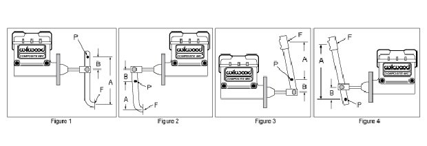
If uncertain about which pedal ratio is right for your application, a 6:1 ratio is an excellent starting point.
A = Distance from pivot point to middle of push / pull point
B = Distance from pivot to point of push on master cylinder
P = Pivot point
F = Force or push - I have a soft pedal. How do I cure the problem?
-
Assuming that your spongy pedal is related to the brake installation and not aggressive braking such as that experienced during racing, the most likely culprit is air in the system. See above for proper bleeding of the master cylinder and brake system. A spongy pedal can also occur for a number of other reasons: misaligned caliper, incorrect caliper/master cylinder bore combination and more. See our complete Troubleshooting Guide for a more thorough list of causes and solutions.
- I have a hard pedal, but the car is very difficult to stop. What is the problem?
-
Common contributors to "hard pedal, won't stop" issues are an oversized master cylinder bore and/or inadequate pedal lever ratio. Another contributing factor is the “aggressiveness” of the pad. Disc brakes require approximately 900-1200 PSI at the caliper for effective functioning. We recommend that you use Wilwood Quick Check Pressure Gauges to measure your pressure at the caliper. If you are not generating the required pressure, we recommend increasing your pedal ratio, and/or going to a smaller bore master cylinder. See our Troubleshooting Guide for more complete information, and make sure you have Wilwood Quick Check Pressure Gauges available to assist you in evaluating the problem.
- Why does my pedal "fade" or "go away" after I've warmed up my brakes?
-
Old brake fluid is the main cause of this problem. Brake fluid deterioration occurs from heat cycling and absorption of moisture. As brake temperatures increase, the old fluid boils, causing the pedal to fade. See our "lose your pedal" section of the Troubleshooting Guide, and make sure you are using fresh Wilwood brake fluid.
- Do I need to use a pressure valve?
-
These in-line pressure valves retain a minimum brake line pressure to help eliminate excessive pedal travel in both disc and drum brake systems. The two pound valve is used in disc brake applications where the master cylinder is mounted below the horizontal plane of the calipers and fluid drain back occurs from gravity and vibration, thereby causing excessive caliper piston retraction and a longer brake pedal stroke. The minimal two-pound residual pressure prevents fluid from flowing back without causing the brakes to drag. With drum brakes, a ten-pound valve is used to compensate for return spring tension in the drums.
- What is a proportioning valve and do I need one?
-
A proportioning valve is a pressure reduction device. It is typically installed in the rear brake line to reduce braking efficiency and compensate for premature rear-wheel lockup; a result of incorrect front to rear brake bias. An adjustable proportioning valve permits incremental adjustments to fine tune brake bias. This ability to adjust front-rear brake bias is particularly important in race applications, as changing track conditions and vehicle dynamics usually require the brake bias be adjusted throughout the race. Normally, you do not need to purchase a proportioning valve with a Wilwood four-wheel disc brake kit. Because Wilwood manufactures calipers with the correct piston area for each application, our kits will work with your dual-chamber stock master cylinder and stock pressure limiting valve. There is no need to modify or remove the existing pressure-limiting valve, and no additional proportioning valve is needed. A Wilwood kit will also work with your ABS control systems. However, if you significantly change your vehicles weight and/or chassis dynamics, such as is common with muscle cars, hot rods, street machines and customs; you will likely need to remove the factory proportioning valve and install an adjustable proportioning valve when installing Wilwood brake kits. The factory valve was designed for a specific weight car, on a specific tire, with a specific suspension system, and a specific amount of brake torque at each wheel. If any of these specifications have been altered, the factory valve will not allow optimum performance of the braking system by either limiting too much pressure, or not limiting the pressure adequately. A Wilwood adjustable proportioning valve will provide easy adjustment to obtain the optimum pressure for your modified vehicle.
- What master cylinder bore size do I need?
-
The master cylinder bore size that you need is dependent on several variables. Choosing a master cylinder bore size begins with defining how the master cylinder will be actuated, manually or with the assistance of a booster, either hydraulic or vacuum operated. Once you have decided on how the master cylinder will be actuated, the information below can be used as a guideline for selecting the right master cylinder. Keep in mind that auto manufacturers have put many years of experience and a lot of testing into determining the right combination for a given car. When building a custom car with changes to the suspension, brakes, tires, and weight balance; you too may need to do some testing to determine which master cylinder is right for your vehicle. The combined piston area and piston volume of your calipers and the pedal ratio, are two of the primary considerations. Whether the system is boosted or not is another consideration. Remember that a larger master cylinder bore produces more volume and a smaller master cylinder bore produces more pressure.
- What master cylinder is best suited for my application?
-
The goal is to select a master cylinder system that supplies sufficient fluid volume to provide a firm, responsive pedal, while generating enough pressure to stop the car comfortably. There are two types of master cylinders, single reservoir, single outlet master cylinders and dual reservoir, dual outlet (tandem) master cylinders. A tandem master cylinder will have two fluid output ports, one for the front brakes and one for the rear. A single fluid output master cylinder, or "fruitjar," will be plumbed to all four calipers as a single system. Dual master cylinder pedal systems are used extensively in racecars and have completely separate master cylinder systems for the front and rear brakes. This setup permits easy adjustment of front to rear brake bias with the integrated balance bar assembly.
- How do I bench bleed my master cylinder?
-
Place your master cylinder in a vise, holding it by the mounting bracket and making sure it is level. Thread one each “3/8-24 barbed fitting” into each of the pressure ports, then attach a six-inch piece of clear plastic hose to each barb. Fill the reservoir with new brake fluid; then place the other end of each hose into the reservoir, one on each side of the wall separating the two chambers. The hoses must remain submerged in brake fluid until the bleeding process is completed. Using full strokes, slowly push the piston in using a Phillips head screwdriver or other device that simulates a pushrod. Do this until ALL of the air bubbles have disappeared from the clear plastic hose.
- I put your front and rear kits on my vehicle, but the pedal goes to the floor? What is causing this to happen?
-
If the brake system has just been filled up with fluid for the first time, and you are having trouble getting a pedal, refer to the master cylinder and system bleeding procedures within this Frequently Asked Questions section. There are several other possible causes, beginning with a sudden fluid loss due to a master cylinder failure or leaky fitting(s). Other causes include: Air in the brake system; calipers not bled with bleed screws straight up; wrong size master cylinder (too small); calipers mounted on an equal plane with, or higher than the master cylinder; calipers flex excessively due to excessive pressure (over 1200 PSI); pedal ratio too great and excessive spindle deflection in corners causing piston knock-back.
- What Brake Fluid should I use?
-
The Department of Transportation specifies three common types of brake fluid: DOT 3, DOT 4 and DOT 5. DOT 3 and 4 are the preferred types for high-performance, high temperature use and are available in a very wide range of formulations and performance characteristics. DOT 3 fluids are usually less expensive than DOT 4 fluids and are not as capable in extreme use. DOT 5 is a silicon-based fluid, which is not good for high temperature use because it expands, becomes compressible, and makes your pedal soft and spongy. DOT 5 is inert and it is not corrosive which makes it good for preserving classic cars because it doesn’t take your paint off in the event of accidental spillage or leaks. Wilwood has versions of each DOT fluid engineered to the specific needs of our customers. Wilwood Hi-Temp is the maximum performance DOT 3 fluid at a cost effective price. Wilwood EXP DOT 4 fluid is the highest temperature, highest performance, lowest compressibility brake fluid you can buy. Our DOT 5 fluid is formulated to protect your classic vehicle and give reliable brake performance.
- Do I need rear disc brakes?
-
Under heavy deceleration the vehicle's weight is transferred to the front axle, requiring the front brakes to do most of the work stopping the vehicle. However, adding improved braking to the rear of the vehicle can improve overall braking performance.
- Are your wide five hubs filled with oil?
-
No
- Can a car manufacturer deny me a warranty claim because I upgraded to a Wilwood brake system?
-
This federal law regulates warranties for the protection of consumers. The essence of this law concerning aftermarket auto parts is that a vehicle manufacturer may not condition a written or implied warranty on consumers using parts or services, which are identified by brand, trade or corporate name (such as the vehicle makers brand) unless the parts or service are provided free of charge. The law means that the use of an aftermarket part alone is not cause for denying the warranty. However, the law's protection does not extend to aftermarket parts in situations where such parts actually caused the damage being claimed under the warranty. Further, consumers are advised to be aware of any specific terms or conditions stated in the warranty, which may result in its being voided. The law states in relevant part: “No warrantor of a consumer product may condition his written or implied warranty of such product on the consumers using, in connection with such product, any article or service (other than article or service provided without charge under the terms of the warranty) which is identified by brand, trade or corporate name....” (15 U.S.C. 2302(C)).